Color Meter:
Lessons Learned
John Peterson
August 2013
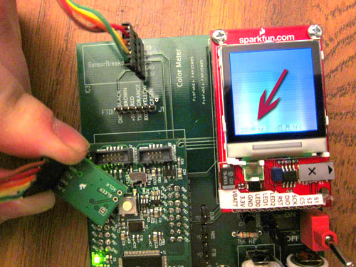
Color meter in operation, measuring a green LED
Hackaday recently put out a call for projects that didn’t work out quite as intended. My efforts at building the Color Meter filled the bill.
The original idea was to build a device for calibrating the colors generated by RGB LED lights. I’d bought a number of different RGB LED devices, and wanted a way to be able to compare the colors from different devices, and to calibrate the colors I could generate driving them with PWM (pulse width modulation).
When the DesignStellaris 2010 contest was announced, I figured this was a good platform to build an interesting color meter with. The chip used for the contest the Stellaris LM3S9B96 was an 80Mhz ARM with 256KB of ROM and 96KB of RAM. The other major gimmick of the chip was additional ROM space loaded up with useful software including a peripheral driver library, boot loader, and a mutil-tasking kernel. This was actually very useful and easy to use.
The contest supplied an evaluation board with an Ethernet jack. I created a motherboard for it with additional circuitry for the color sensor, a small color LCD display and a battery power supply. When completed, the device did measure colors and provided several different readouts on the color LCD display, including a nice interactive color chart. It received an Honorable Mention in the contest.
So what’s the problem? Why do I consider the project a failure? Foremost, it was utterly useless for the intended application: measuring the color of PWM driven color LEDs. It turns out the color sensor chip I chose had a very short integration and measurement time, and was useless at measuring LEDs driven by PWM. So I could measure solid colors fairly reliably, but for strobing LEDs, it proved useless.
So here’s a collection of lessons learned from this project:
Do Not Select a Critical Component Just Because Sparkfun Sells a Breakout Board for it.
Obviously, if you’re building a color meter, the color sensor chip is a Really Important Component. I sourced the one Sparkfun was selling (based on the Avago ADJD-S371-QR999) at the time without doing much further research. The key problem for me was the documentation never explained the absolute range of values the sensor handles, nor how the calibration and range values corresponded to any sort of real-world units. There were also no clues about the timing used by the chip’s sampling, though it was very clear it was a much shorter interval than any typical PWM LED. Fully understanding this component (and likely choosing a different one based on my intended task) would’ve made the project much more successful.Read and Pay Attention to the MAX756 Spec Sheet
The power supply for the project was based on two AA’s boosted to 5V using a Maxim 756. This design was based the original Minty Boost, and I’d used it successfully in a previous project. But when I first brought up the board, things worked, but not well. The CPU would reset. The display would fill with glitches. The code would freeze up.Previous experience with random glitchy behavior led met to suspect the power supply. When I zoomed in with my scope, sure enough, there was all sorts of noise and ripple on the supply.
It turns out, when I laid out the board I put power supply components in convenient locations, forgetting the MAX756 spec sheet’s admonition to keep the ground leads of C1 and C2 less than 5mm and other connections “as short as possible”. Yes. I pulled off the distant parts and soldered them directly to the leads of the MAX756 underneath the board. Power was much cleaner and the flaky problems went away.
Nokia 6100 LCDs are Evil
At the time I started this project, this was one of the few color LCDs readily available on a breakout board. Programming them is a dreadful experience. First, they have two different controllers, and you’re never quite sure which one you’re getting. Only one of the advertised data transfer modes worked. Certain columns of the display simply couldn’t be written. And the quality of the display is a bit washed out looking. Fortunately the world has moved on; much better color LCDs are available at similar prices that are much easier to interface to.Don’t place the + and – battery clips right next to each other.
The batteries tended to short when they were installed and removed. This mistake was easily fixed with some tape, but future layouts should leave plenty of room for the clips as they spread when batteries are installed.Do Not Base Designs on Unobtainium Dev Boards
After working on the project for a while, I discovered the LM3S9B96 dev boards were made only for the contest, and once they were distributed to the participants, no more were available. Fortunately, mine is still working, but it was heartbreaking to read forum posts from participants that had their dev boards fail and were forced to abandon their work because no replacement was available.Do Not Base Designs on Unobtainium Toolchains
The software toolchain used to compile code for the LM3S9B96 (and its built-in device and RTOS libraries) sold for around $2,000 at the time. Contest participants were given a “free” copy that timed out shortly after the contest ended. Needless to say, this caused me to stop working on the project when the contest ended.
So the project does work. You can hold different colored objects up to the sensor, and the cursor floats to the corresponding spot on the LCD’s color chart. The built-in RTOS of the LM3S9B96 also worked well. I had the LCD update, polling the sensor, managing the controls and updating the web data all running as separate tasks, and it worked very smoothly. But as the tool I’d hoped for calibrating color LED output, it was a failure.