Wire-wrap Days
John Peterson, October 2011
[based on work done a few decades before]
contact102 {at} saccade.com
I'd thought about posting these projects for a while, but the Open 7400 Contest finally spurred me on to do it. Looking at the rules, I didn't see anything about when a project needed to be done, so I thought it might be fun to post something that was built with discrete 7400 logic, because, like, that's how you actually made stuff. We'll, OK, we did have microprocessors then, but using those didn't teach you much about logic or hardware design. Spending six months of your life with a wire-wrap gun and a pile of 7400 chips did.
The Class
The classes at the University of Utah, winter and spring quarter, were CS427 and CS428, Digital Hardware Lab. It was the classic "weeder" course. As I recall 70+ signed up for the first quarter, but there were less than a dozen of us still at it by the time summer rolled around. There were frequent 30 hour days to make lab deadlines. But if the surviving students put a lot of work into it, Professor Hayes did too. I remember during the spring quarter he would frequently meet with students one on one to make sure their design wasn't headed off into the weeds. Trust me, that level of faculty interaction with undergrads was (and probably still is) unheard of at a big state university. The TA for the class (Bob Elens) also spent many hours reviewing designs and lab books.
The Suitcase
A unique facility of the hardware lab classes was The Suitcase issued to each of the students. Designed by the department's lab manager (John Ellsworth, if I recall) the suitcase contained everything you needed to prototype some seriously complex designs.
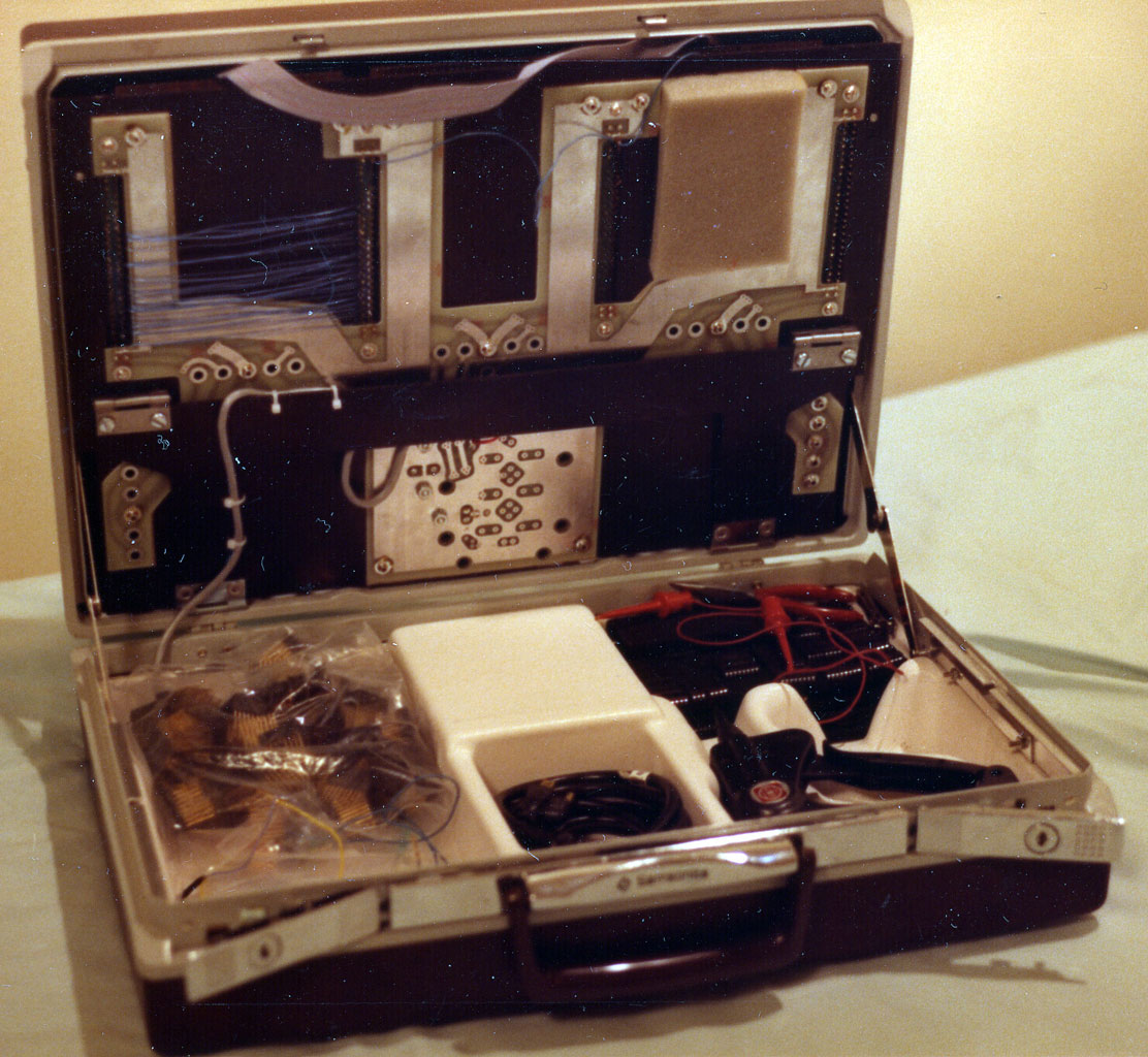
Inside there was a hefty metal plate on top with mounting hardware for four or five wire-wrap proto boards, and edge connectors so you could hook them together. This tilted forward to make a nice work area. Underneath was a beefy 5V power supply, and storage bins for tools (including the all-important wire-wrap gun), parts including dozens of chips stuffed into black foam pads, bypass caps and other passives, LEDs, a few switches, and packets of pre-stripped wire. Overall the suitcase lab was a really clever, effective design.
Most all the chips were SSI/MSI gates and latches based on 74Cxx logic. These were chosen because the lower-power CMOS devices were less likely to fry themselves in case of student wiring blunders. The only concession to LSI chips were some 2716 UV Erasable ROMs and some SRAM.
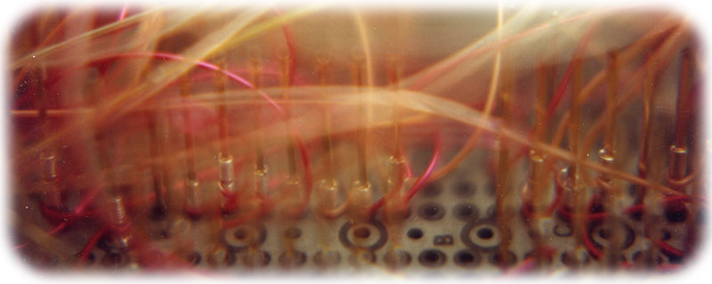
When you got your suitcase, the first order of business was unwrapping the previous student's efforts (the loopy board up top was the previous student's...my work was slightly neater than that.)
The Calculator
The first few weeks of the first class were spent doing simple labs, mostly to teach students how logic worked, how to use the tools, how to debug, and how to write up your designs. Then you launched into the meat of the class: Design a four digit, stack-based (a la HP RPN) calculator that could add and subtract. Sounds simple, right? Well, remember you're doing everything with gates and latches. Scanning and debouncing the keyboard matrix, multiplexing the LED digits, managing the stack and computations. By the end of the quarter you had filled three boards with chips.
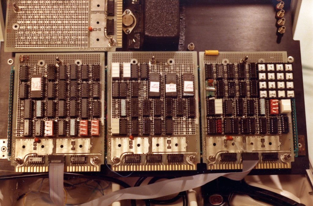
Three calculator boards: Stack & ALU, State Machine, Clock & Keyboard
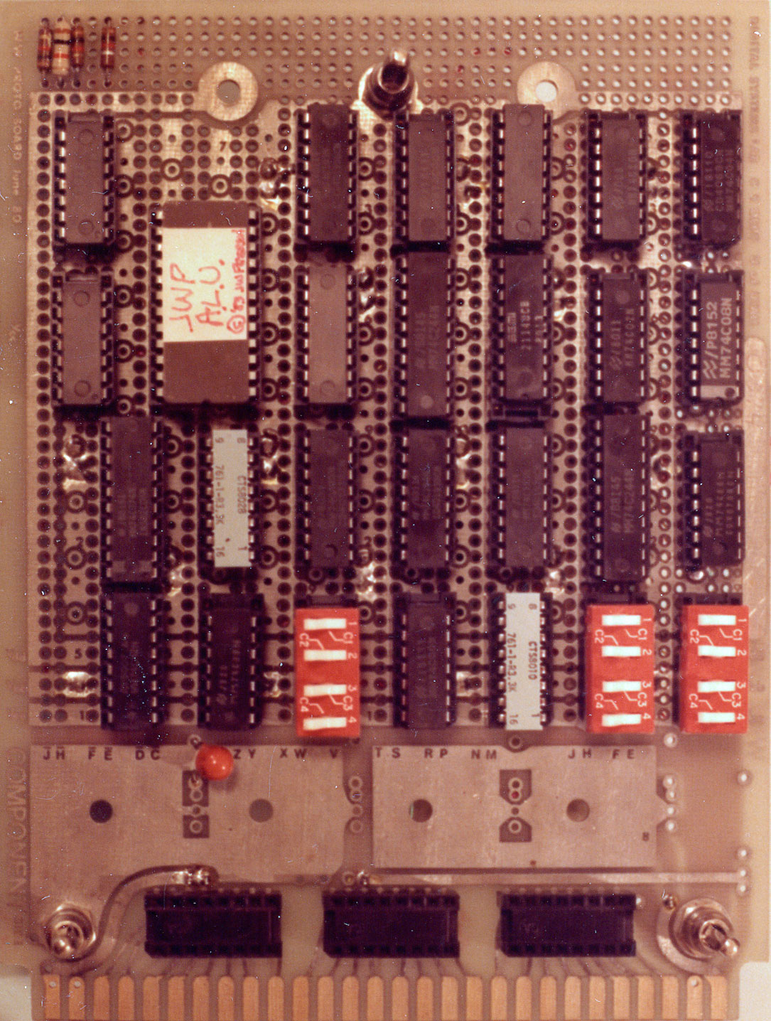

ALU Board, top & bottom
Our designs were based on micro-coded state machines. This made it relatively easy to edit and debug the system operation by single-stepping the clock, and re-burning an EPROM if you messed something up. The prospect of creating an EPROM layout for the microcode by hand was pretty daunting, so (being a software guy) I came up with a basic micro-code assembler. It's written in RLISP - a long dead dialect of Lisp wrapped in Algol-like syntax. It was a huge improvement over trying to set the microcode ROM bits by hand. Once Prof. Hayes caught wind of this, he implored me to document and generalize it so the rest of the class could use it. I think the majority of the class did.
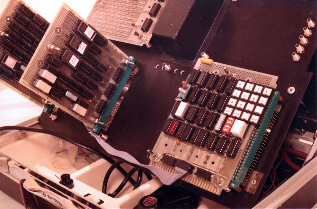
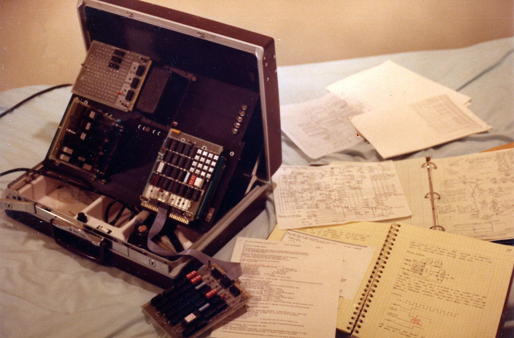
Calculator, set up for operation
I also programmed one of the 2716 EPROMs to serve as an ALU. Again, a bit of RLISP code generated the bit pattern for that.
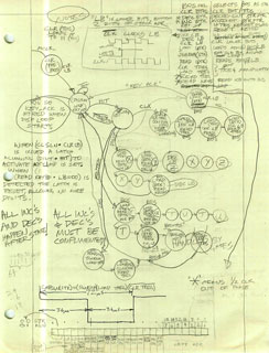
We were required to document our designs in the notebook (which I did, longhand). Schematics were done in pencil on drafting vellum, using plastic templates for the various logic and schematic symbols. But really, most of the calculator design happened on one piece of graph paper, where I kept track of the microword, the state machine, and most of the signal names.
The calculator worked..er, mostly. As I recall, it had issues with subtraction, but addition and the stack operations worked according to spec.
Calculator Documents
Calculator Schematics [PDF 600K], Lab Notebook [PDF 18MB]
- Microcode Word layout
- MakeALU.RED source
- Calculator microcode source
- Calculator specification (Lab assignment)
- Makecode - Microcode Assembler documentation
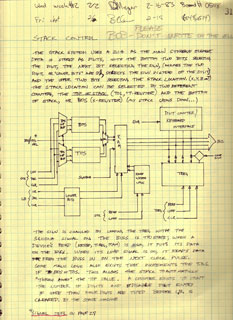
The Computer
The entire spring quarter was devoted to a single project: A working computer with serial I/O and a lights 'n switches front panel. Architecturally, it was an 8-bit CPU that was sort of a PDP-8 with some PDP-11 overtones. It had a single accumulator, basic arithmetic (+,-,&,~,<<,>>), conditional branching and subroutines (but no stack). It could address 10 bits (1K) of RAM.
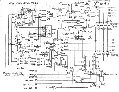
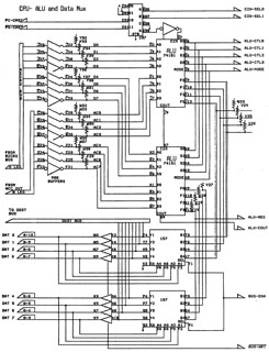
During the previous quarter I'd grown jealous of the students who had access to their employer's CAD systems to do their schematics on. Their work looked way better than my smudged pencil drawings. Over the winter break I decided to do something about it. Thanks to a part time lab job for one of the professors, I had access to one of the original Apollo workstations. I quickly wrote a simple drafting program, called Gates (as in "logic", not "Bill"). I created a special font with the various schematic symbols, and used the cursor keys to draw lines, place symbols and write text. To erase something, you switched the color, and over-wrote the previous symbols, and then switched the color back. All these actions were logged to a file, and played back when I started a new session. You got an amusing replay of all your activity every time you started. It was a $10,000 Etch-a-Sketch, but the drawings looked good. Printouts of the bit-mapped screen were done on the department's Versatec electrostatic printer, one of the few devices around then able to actually print bitmap graphics. The Versatec's prints had lousy contrast and foul smelling toxic paper, so you quickly xeroxed them to normal paper before the original faded away.
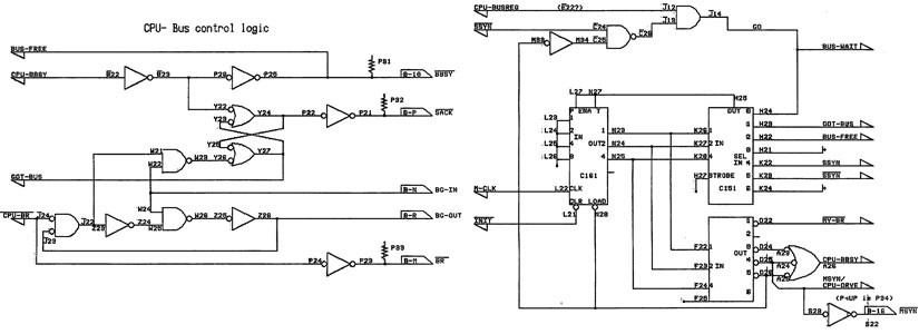
Sample schematics - numbers by each pin correspond to wire-wrap board coordinates.
This class was even more intense than the previous term. Toward the end of the quarter, students essentially lived in the hardware lab, frantically trying to get their systems working. Once, I walked in and discovered somebody sound asleep - on a hardwood lab bench. Since I worked for the department, I was able to sneak into a chip designer's lab and borrow their four-channel Tek scope. I also recall a lot of time spent burning and re-burning microcode EPROMs.
By now, you might be wondering where this system is today - where are the photos? The YouTube video?
Um, yeah, about that.
Recall the suitcase had to be turned in at the end of the quarter. And my system started working about 10 minutes before the quarter officially ended. As I wrote in my lab notes:
...After five iterations of the test program (over a period of about two minutes) the CPU was powered off and torn apart. It probably has the record for the shortest operational life of any computer system in history.
I do still have this nice annotation from my grade sheet though:
In the end, that's what really counted. I think there were only two or three other working systems in the class.
So ended three of the most intense months of my life. But the knowledge of how computers work at their very lowest level remains, and that's a very satisfying thing to have. There's no magic left about how silicon is turning bits in memory into a video game or text editor.
Computer Documents
- Computer system specification (Lab assignments) [PDF 2MB]
- CPU Microcode source
The class left me with a deep appreciation of people who've built their own systems just to learn how it's done. Some examples:
- Big Mess 'o Wires
- Apollo Guidance Computer - Rebuilt in TTL
- Magic-1
- MT15 - built out of transistors
- Harry Porter's Computer - hand built using relays
- Zuzsie - Another relay computer
- Homebrew Computers WebRing page.
![]()
Homebuilt CPUs WebRing
JavaScript by Qirien Dhaela
Join the ring?
To join, drop Warren a line, mentioning your page’s URL. It will then be added to the list. You will also need to copy this code fragment into your page.