
John Peterson, 2008
contact102{at}saccade.com
First Place, Third Annual Lantronix
Wireless Design Contest
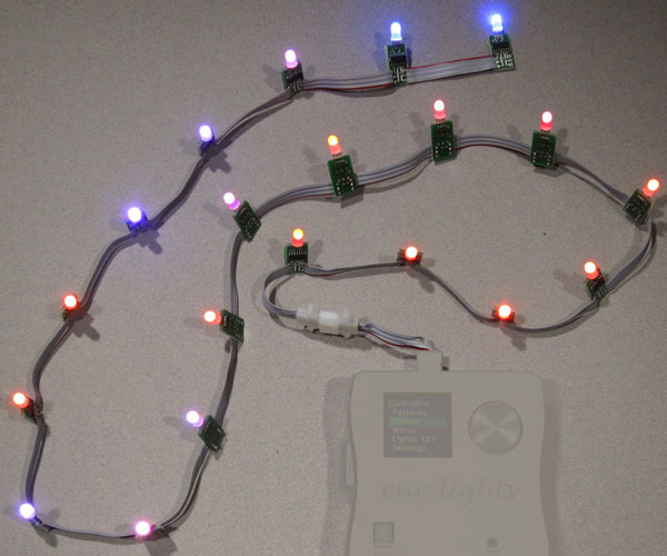
By now, the WS2812 has taken over the blinky-LED universe. But several years ago, if you wanted a string of blinky LEDs, you had to blink them yourself. This is the story of one solution to the problem.
It started around 2007. I ran across a web page featuring Triklits, a string of RGB LEDs you could program the colors of. They looked like fun, so I tried to order a set. I was told they were out of production at the time, but after waiting several months, it was clear they weren't coming back any time soon. Time to roll my own.
Design
I wanted the light string to be:
- Full color
- Animated
- Individually addressable
- Easy to control
It didn't take long to arrive at the idea of having a micro-controller (MCU) per LED, to handle the task of doing the pulse width modulation (PWM) to control the colors of each LED. The MCU also handles addressing the LEDs, storing and synchronizing different color values for animation, and fading between different color values.
The string uses a simple daisy-chained serial protocol for addressing the lights. The serial output of one light connected to the serial input of the next, and the lights automatically assign themselves addresses when initialized. I came up with a clever synchronization scheme for animation where the first lights in the string delay changing the values until the change message reaches the end of the string.
Protocol
The serial protocol for controlling the lights consists of a one letter command, followed by one or two bytes of parameters. The parameters are:
- <ID>
- A seven bit light identifier (0..127). The first light (<ID> zero) is the light closed to the serial port controlling the string. The light IDs increment up from that.
- <color>
- A nine bit color, specified as three bits of red, three bits of green, and three bits of blue. But wait - bytes only have eight bits?! Yeah, the ninth bit (the MSB of the red color) is stored as the eighth bit (MSB - most significant bit) of the the <ID>. That's why the <ID> is limited to seven bits (0..127).
- <frame #>
- A frame number. The current implementation is able to store 80 "frames" of nine-bit color values. This could possibly be increased.
- <pwm>
- This specifies a PWM value. This is not normally used while using the lights, but is provided as a development aid for calibrating the brightness values. Since PWM values range from 0..511, we again have a nine bit value. Like the color value, the MSB of the <pwm> value is tucked into the eighth bit of the <ID>.
The full protocol is presented here. The gray entries are special commands for the first light in the chain to control the animation, but aren't implemented yet.
| Name | Specification | Description |
| Init | I<ID> | Sets the IDs of this and subsequent lights Sets LED to color corresponding to ID |
| Init | i<ID> | As above, but doesn’t change light color |
| Color | C<ID><color> | Sets LED at <ID> to <color> (cur frame) Note high bit of <ID> is MSB of red color |
| Dest | D<frame #> | Sets dest slot for frame color (all lights) |
| Frame | F<frame #> | Sets displayed frame (all lights, not synchronous) |
| FadeTo | f<frame #> | Fade to displaying frame (all lights, not sync) |
| Step | S | Steps one forward in the animation (synchronous) |
| Step | s | Fades one forward in the animation (sync) |
| Time | T<ticks> | Sets the duration of each animation step |
| Run | R | Starts the animation at frame 0 |
| Halt | H | Stops the animation |
| Number | N<count> | Broadcasts the light count (used for animation sync) |
| End | Z | Marks end of transmission (not sent to lights!) |
| redPWM | r<ID><pwm> | Sets Red PWM value to pwm Note hight bit of <ID> is MSB of pwm value (0..511) |
| grnPWM | g<ID><pwm> | As above, for green |
| bluPWM | b<ID><pwm> | As above, for blue |
Initial Prototype
For the MCU, I chose the Microchip PIC 16F688. It's cheap, fast enough to process the PWM, and it has a built-in serial port. It's available in both DIP and TSOP packaging, making it easy to prototype with. A special "debug" version of the chip is available, which I found very useful for development. The architecture of the chip is a bit odd, but fortunately I found an efficient C compiler for it and didn't need to resort to assembly language. Still, packing the design's variables- PWM, serial protocol, animation, etc. into 256 bytes of data (not kilobytes - bytes) is an interesting challenge.
Another great thing about using the 16F688 is the low parts count. Each light has just the MCU, the LED and three wires connecting to the next LED in the string. By adjusting the PWM values, I was able to avoid current limiting resistors, and the 5V supply used by this MCU provides plenty of headroom for driving the LEDs. In retrospect, a bypass capacitor on the supply rails probably wouldn't be a bad idea.
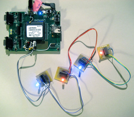
Original prototype
For the first prototype, I implemented the lights on perfboard using DIP MCUs, and used a Lantronix Matchport WiFi serial interface to talk to the LED string. The choice of the Matchport was influenced by entering the project in the Lantronix Third Wireless Design Contest. The project did spectacularly well, winning First Prize as well as the "Most Likely to Succeed" prize. The contest is the only one I've entered where the actual prototype had to be packed up and sent for evaluation. The prize included a free trip to San Jose to receive the award at the Embedded Systems Conference that year. Ironically, I work in San Jose most every day, so the "trip" was a four block walk. (For the contest I originally named the project "Versalights". I later discovered somebody else uses that name for a commercial product, so I changed the name to Curilights.). A more detailed design document (originally written for the contest) is available.
Next Revision
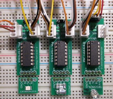
For the next revision, I designed some printed circuit boards for the lights. One board is a generalized "test bed". This is a string of eight lights wired together.
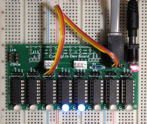
Each of the MCUs is socketed, making it easy to swap in the debugging header. The flat gray cable connects to a PIC programmer/debugger such as the Microchip ICD-3. The yellow/orange jumper connects the programmer to one of the individual MCUs on the board. The connector at the top left of the board (labeled "J26") is a set of pogo-pin connectors for programming individual lights. The keyed white connectors allow hooking up other breakout boards to the string of lights. Only three of these connector's four pins are used, but I like using keyed connectors, and the four pin ones were more readily available.
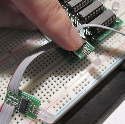
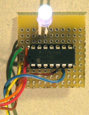
Programming individual MCUs on the finished string.
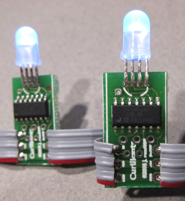
I also created break-out boards for the MCU and various different LEDs separately. This makes it easy to "audition" different RGB LEDs by plugging them into a breadboard. Again, the white connectors string the lights together, and the three pin connectors on the top are for programming/debugging the MCU.
For the first strings of lights, I used a TSOP package for the MCU, and through-hole RGB LEDs. For the first few strings I actually tinned and stripped the ribbon cables myself (agonizingly tedious). I later discovered you can buy pre-stripped and tinned ribbon cables - Thank you Molex!
Future Work
Despite the WS2812 invasion, I still plan future developments for the Curilights. On the software side, it's interesting to take advantage of the non-voltile memory storage available on the 16F688 MCU. The chip allows storing up to 256 bytes retaining their values after the power is cycled. This way the lights maintain patterns or animations without any controller connected - something the WS2812's can't do.
I also plan to clean up the form factor. By using surface mount LEDs and placing the components in line with the connecting ribbon cables, the string of lights will fit in 1/2" tubing. This way the electronics are hidden away and can be made weather-proof as well.
I've created a controller for the Curilights based on the mbed platform.
![]()