One of the cool things modern tech has made straightforward is the ability for gadgets to balance themselves. Spinning reaction wheels allow a device to change its position and hold it in place, even if it’s balancing on a point. Last century, this would have been a major (and expensive!) engineering challenge. Today inexpensive nano-tech gyroscopes, direct-drive motors and microcontrollers have reduced automatic balancing to an engineering class project.
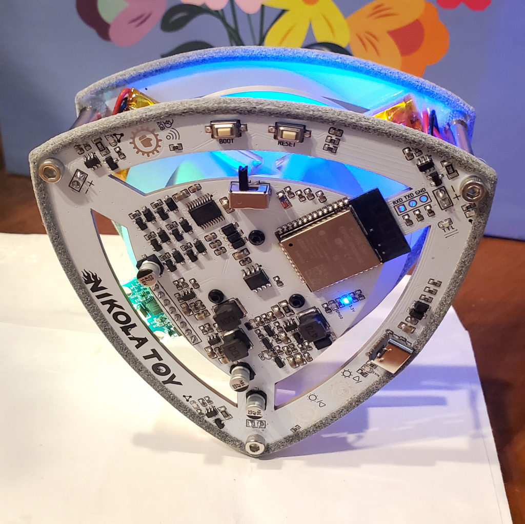
I’d love to learn more about this and build such a device. Check out this YouTube channel for a whole variety of homemade balancing devices. In the mean time, you can buy a fun demo from Nikolatoy: The Lelo self-balancing triangle. This is a commercial version of an open-source project that apparently is very popular in China (YouTuber RemRC’s version is here).
One of the clever tricks Nikolatoy used to reduce the cost of their triangle was to make the frame out of the circuit boards. Unfortunately, the edges of the boards have poor traction, and it’s difficult for the triangle to balance itself without getting stuck slipping back and forth.
I solved this by creating a set of “boots” to put around the edge of the boards, giving the triangle a lot more grip.
This dramatically improves the ability of triangle to function (see the video below). I’ve posted the STLs if you want to print your own, using a soft, flexible material such as TPU. Or, (shameless plug!) you can simply buy a set of them from me on Shapeways (remember to order two of them). [Sadly, as of July 2024, Shapeways.com has gone out of business. You can find other venders by googling “TPU 3D printing services”]
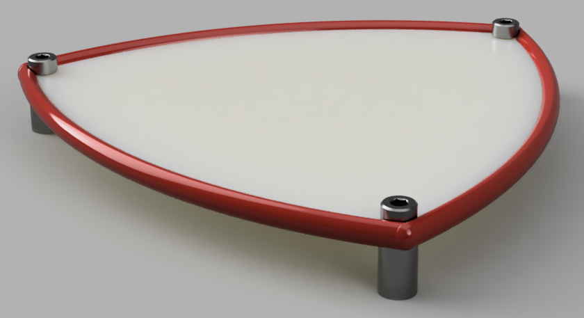
Fantasy version of the fit testing set, milled to the micron in stainless steel
How Accurate is Your 3D Print? I Tested Several Services to Find Out
Update January 2025: Added a few more prints from Jawstec and JLC3DP.
Update September 2024: Several of the entries in this post referred to services (e.g., Shapeways) that are no longer in business, or 3D printing tech that is now obsolete. I’ve archived these old reviews elsewhere, but removed them from this post for brevity. Even though Shapeways is no longer around, I left the story about their process variations as a useful story of what can happen even with a particular process at a specific vendor. This post has been updated with reviews of several contemporary services.
Decades ago, if you wanted to create your own printed circuit board, you had to make it yourself. This was quite involved – you bought a copper plated blank board, created the circuit patterns on it with resist (tape, rub-on patterns, or Sharpie), then dunked it in noxious chemicals to etch the unmarked copper away. It was also up to you to drill the holes. Then you tracked down problems because too much (or not enough) copper was dissolved, opening or shorting your circuits. It was messy, tedious and frustrating.
Here in the future, all those problems are solved. You design the board in a CAD program, then the Internet whisks the design to a far-off fabrication house. A few weeks later your boards arrive, perfectly manufactured with solder masks, silk-screen markings, plated through holes – things you’ll never get making them at home.
I do some amount of 3D printing, but I have no desire to own a 3D printer. Running your own 3D printer still feels like those early days of homemade circuit boards. The tedious details of bed leveling and heating, getting the model to stick in place, support sprues, filament moisture content, speed settings all have to be carefully looked after to get good results. I prefer the modern circuit board model for 3D prints – send the model off to a factory with equipment and materials you’ll never afford, and get your polished results back in the mail.
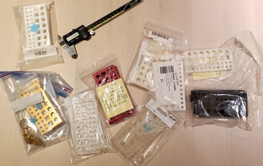
When I started ordering 3D prints, I had a basic question: when designing two parts that fit together, how much space do you need to leave between them to fit properly? To research this, I designed a set of fit-testing sets and printed them with various processes to see what sort of tolerances are necessary. So far I’ve tried nine different prints, and (unlike circuit boards) the results vary considerably.
The fit testing sets consist of two parts, a pair of pegs, each with round and square ends. One peg has 5mm ends, the other is 10mm. The other component is a block with a range of holes of different sizes to test fit each peg. Printing these and testing which hole each peg fits in helps to determine how much extra margin your design needs to have parts fit together well. For example, if the peg fits comfortably in the +0.2mm hole, that means you’d better leave a 0.2mm gap in your design for the parts to work smoothly.
The first blocks I made ranged from -9.85 to 10.15 (in increments of 0.05mm) for the large holes, and -4.875 to 5.125 (with 0.025mm steps) for the small ones. I quickly discovered this wasn’t enough range for coarser printing processes, so I created additional blocks with wider ranges of 9.7 to 10.3 (9.75 to 10.25) and 0 to 0.6 (0 to 0.5). These doubled the increment steps of the previous blocks, from 0.05 / 0.025 mm to 0.1 / 0.05.
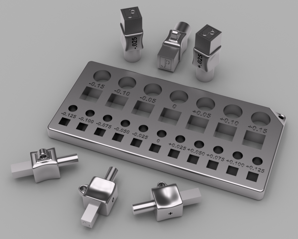
The last block works well for the coarsest printing technologies, and is the best place to start for basic FDM (fused deposition modelling) printers. The rendering above also shows some quarter-step peg sets I modeled for even more precise tests, but you won’t need those anywhere outside of a Swiss watch factory.
Over the past few years I’ve printed blocks and pegs with a number of different services, to get a feel for the accuracy and tolerances of each. Read on for a review of what I discovered.
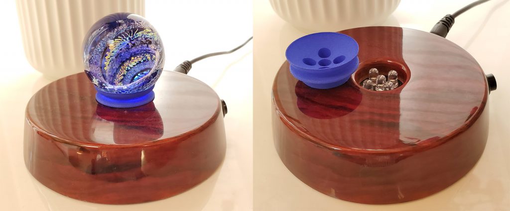
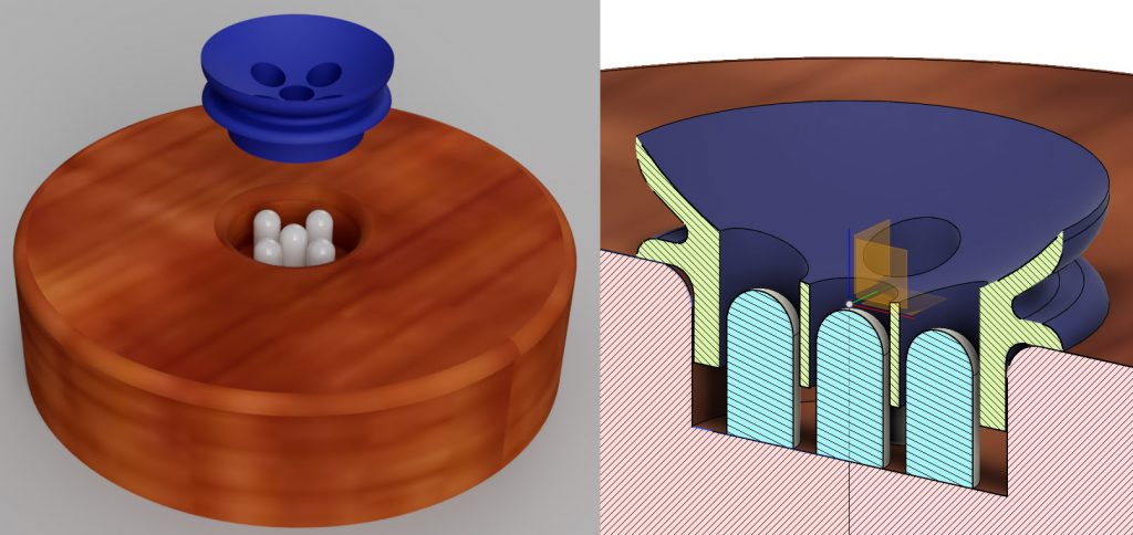
On a recent trip I picked up a art-glass marble for my wife. She liked it so much she bought a nice lighted display stand for it. The stand wasn’t designed to display that particular marble though, so it didn’t work too well.
This was a problem easily solved with a bit of 3D printing. I figured it’d be trivial to make an adapter ring for the marble to sit securely on. However, when I examined the stand, I discovered the LEDs were flush with the base, and likely to get in the way. The marble needed to be held up above them. Before starting on the adapter, I did a simple model of the stand, so I could check everything cleared.
With the stand and LEDs modeled, I could verify my design properly fit. The project worked great, and fit perfectly with the first print. Success.
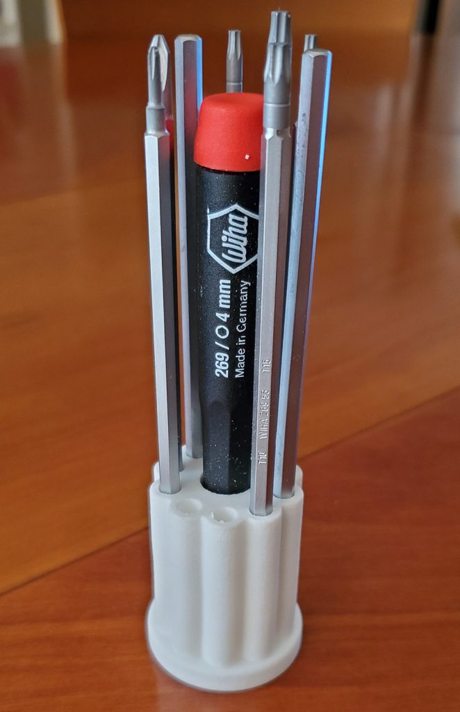
The next CAD project I did was a stand for a screwdriver set I purchased. I carefully measured the handle and the various blades, but (perhaps over-confident) didn’t bother to model them.
It wasn’t until I got the print back I discovered a major ergonomic fail: You can’t easily reach the handle because the blades are in the way! Had I taken the time to actually model the blades and handle, I would have visualized this immediately, and chosen another layout.
Moral – it’s a good idea to model the whole environment, not just the piece you’re printing.