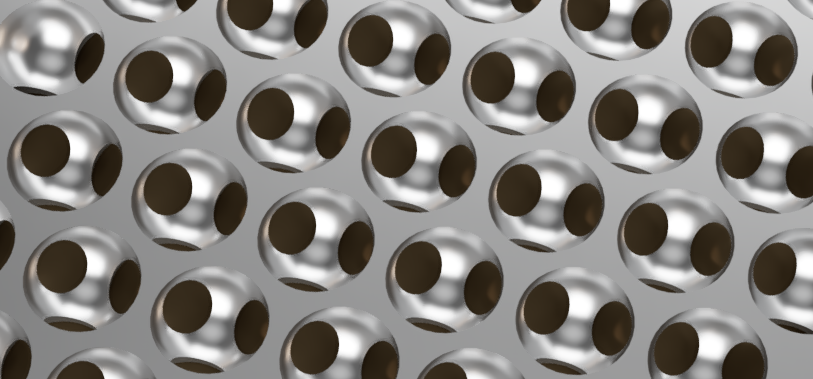
Apple’s recently introduced Mac Pro features a distinctive pattern of holes on the front grill. I’m not likely to own one anytime soon (prices for a well configured machine approach a new car), but that pattern is very appealing, and re-creating it is a fun exercise.
The best clue about the pattern comes from this page pitching the product. About halfway down, by the heading “More air than metal” is a short video clip showing how the hemispherical holes are milled to create the pattern.

Let’s start with a screen grab of the holes from the front. The holes are laid out with their centers equally spaced apart and the tops of the lower circles fall on the same line as the bottom of the circles above them. So the circles are spaced 2r apart vertically, where r is the radius of the circle.

The horizontal spacing is a bit more work. The angles of the equilateral triangle formed by the centers are 180°/3 = 60° (or π/3 as they say in the ‘hood). If you draw a vertical line from the center of the top circle to the line connecting the centers of the bottom circles, that line (as you see above) is 2r long. With a bit of trig, you can find half the horizontal spacing x by using the right triangle formed by that line, x and the side of the equilateral triangle. The angle from the vertical center line to the equilateral triangle edge is half of π/3, π/6. So,
\[x=2r\tan \frac{\pi }{6}\]
and 2x is the horizontal spacing of the circles.
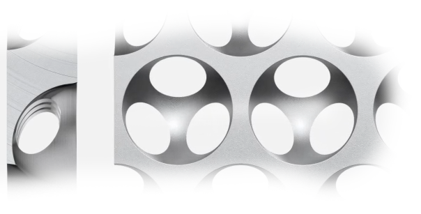
The hemispherical holes are milled into both sides of the plate, but the holes on the other side are offset so the hole centers on one side fall exactly in the middle of the triangle formed by the hole centers on the other side:
You already know the horizontal offset for the centers from one side to the other is x, but how far up do you go to hit the center of that triangle? Let’s call that h.

You’ll use the same tan(π/6) trick we used above, this time using the triangle formed by x and h. Like the triangle used to find x, the angle here is also π/6. So:
\[h=x\tan \frac{\pi }{6}\]
Let’s clean this up a bit:
\[h=x\tan \frac{\pi }{6}=2r\tan \frac{\pi }{6}\tan \frac{\pi }{6}\]
\[\tan \frac{\pi }{6}=\frac{1}{\sqrt{3}}\] so…
\[h=2r\frac{1}{\sqrt{3}}\frac{1}{\sqrt{3}}=\frac{2r}{3}\]
There’s still the issue of how thick the plate is, relative to the size of the holes. I took screen grabs of the film clip and compared them by counting pixels:
Examining the images, the thickness was about 101, with the diameter (2r) of the holes coming in at 176. Now, these numbers aren’t at all precise, because of the perspective introduced by whatever animation software was used. But I can’t help but notice the following coincidence:
\[ \frac{101}{176}=0.573\approx \tan \frac{\pi }{6}=\frac{1}{\sqrt{3}}=0.577\]
Yeah. The ratio of the plate thickness to the hole diameter is just like the ratio of the hole horizontal spacing to the hole diameter. So let’s turn this around, and summarize by saying for a plate of any thickness t, use:
\[r=\frac{t\sqrt{3}}{2}\]
\[x=2r\tan \frac{\pi }{6}=\frac{2r}{\sqrt{3}}=t\]
\[h=\frac{2r}{3}\]
Where r is the radius (half the diameter) of the spheres and 2x is the horizontal spacing of the sphere centers on a given row. For the next row, the centers are offset by x horizontally from the centers of the previous row. The rows are spaced 2r apart vertically, from sphere center to center. The same grid of spheres carved into the back side is displaced by x horizontally, and h vertically from the spheres in the front. The centers of the front spheres are on the front surface of the plate, the back spheres on the back.
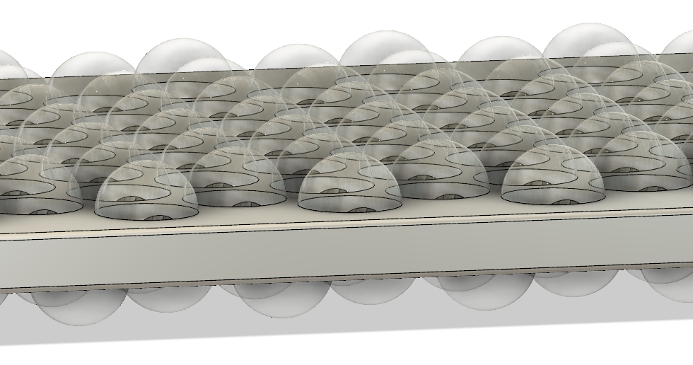
So to CAD this up, all you need to do is start with a rectangular block of thickness t, and use the formulas above to place the centers of the spheres (with diameter 2r) on the front and back of the block.
If you just want to quickly print or look at the result in 3D, I’ve posted some sample STL files on Thingiverse.


